
The second revision was short lived. I made a printed circuit board (PCB) to hold the video transmitter, to avoid having the pads pull off. I switched reed switches and was still using an off the shelf battery charger.
I never built a complete one, only the circuit board. I was still having problems with the reed switches welding themselves, but it would show up after a hundred cycles or so. The system had some form of high current start that I wasn’t able to detect with my multimeter.
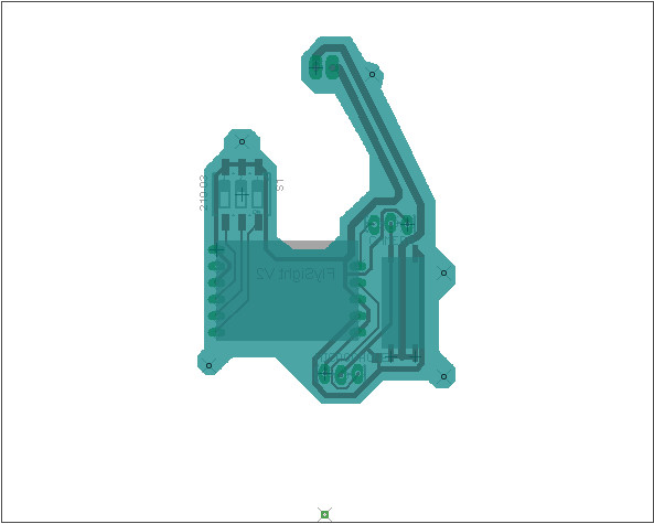
This design was good for me, building this first simple circuit board was easier then I thought it would be. Emboldened I decided to expand the circuit board for V3 . . .